Maypole Antenna Construction Project
By KC7JOG
Introduction: Mark Coker, KC7JOG has designed this “Maypole” antenna that has proven to be an extremely effective antenna. It is constructed in such a way that it can be used as a portable antenna when used in conjunction with the Pushup Pole (another construction article). A growing number of hams are using this antenna here in the Southwest and everyone that has one has a signal that consistently is above those with similar equipment but another type of antenna. We use the antenna mostly on 40 and 80 Meters however it can be made to work on any band, determined by the length of the elements used. The property of this antenna is such that it works well for both local, short distances, and long distances, and it is nearly omni-directional. Mark is blessed with a really good workshop with tools that many of us won’t have, but where there is a will, there is a way. 73, Warren Andreasen, K7CWA
A brief description of the Maypole antenna would be a pole (30’ or so) with a platform on the top, a coax connector, and antenna elements (sloping wires) that go out in different directions, like the classical inverted “V” antenna.
Making the platform:
(Click Image for enlarged picture)
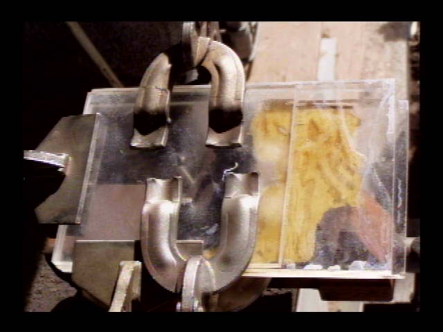
There are 3 pieces of 1/4" Plexiglas that are all over 7" by 7” being glued together in this picture. Platform thickness will be 3/4"
 The material I use is Plexiglas, and I use acetone to stick them together. If you use Lexan, then Super Glue works great. After glue has dried, cut finished size to approx 7" by 7" and sand all sides to a smooth finish,
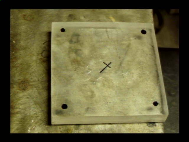
 then mark center of plate, as well as the 4 corners for drilling.
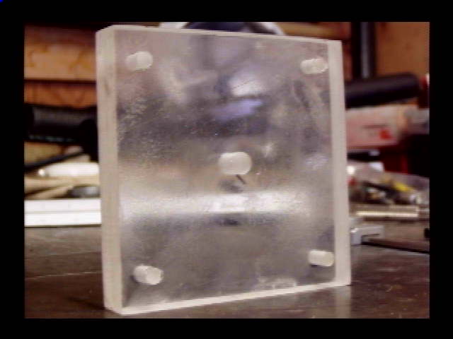
 The 4 corner holes drilled, are 1/4", the center hole is 3/8”
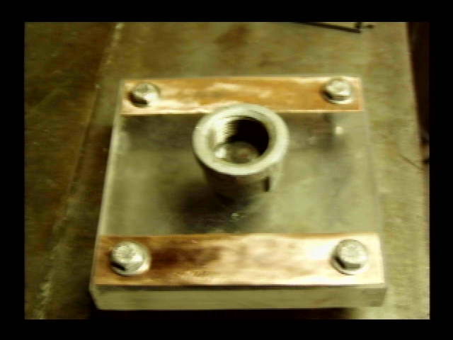
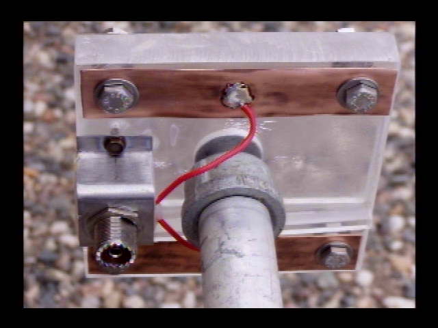
 To make copper strap, cut 1/2" copper tubing in half, then pounded each half flat. Cut to length, then drill them with 1/4" holes to match the holes in antenna platform. To accommodate a mount to the push up pole, grind flat the top of a 1/2" pipe cap, then drill a 3/8" hole in the center of the cap. Placed a 3/8" bolt thru both the pipe cap and the Plexiglas. This allows the platform to be mounted to the push up pole.
 Note the block of Plexiglas, glued to the center of the top of the platform. This separates the set of bolts that are fed by the center of the coax, from the bolts fed by the shield side of the coax. This finishes out the platform, and should eliminate possible moisture related problems.
 Those that want the convenience of a SO-239 for coax feed, here is how I did it. 1 1/2" strap drilled to accept the so-239, with wires of equal length soldered to both the center and ground side of the receptacle. Number 16 wire is great. Bend bracket according to photo, and drill mount holes on bracket.
Should the builder not want to go to the trouble of mounting an SO-239, drill another 1/4" hole in between the copper straps, and feed the RG-8X coax thru the platform. Glue or cement the coax on top, as well as the bottom of platform. This prevents the weight of the coax from pulling itself away from, and out of the platform. Hardening silicone or contact cement can be used. be sure to leave enough coax to strip back, above the platform top. Separate the shield from the center lead, and solder of each of these leads to the centers of both copper straps.
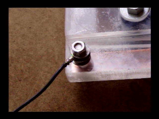
 You may notice that after I mounted the SO-239 bracket to the platform, I sealed the cavity of the SO-239with hot glue. I did this to eliminate moisture causing possible problems should there be rain during the usage of antenna. If you look closely, you will also notice the small 1/4" by 1/4” Plexiglas strip that I glued to the platform base between the copper strap that carries the center coax lead, and the frame of the SO-239, or shield side. This further eliminates possible problems, should water be present during operation.
 Another view of the Plexiglas strip. Note the sealing of the SO-239 assembly by the application of hot glue
 This completes the maypole platform. use 234 divided by the frequency, to give you the length of wires (in feet) needed for the 75 meter, as well as 40 meter band Inverted V's. One 40-meter wire, as well as one 75-meter wire will go to one side of the upper weather Plexiglas barrier. in other words, one wire from each band, share a common copper strap. The other half of the 40 and 75 meter wires, go on the opposite side, sharing the other copper strap.
Wire for the Inverted V's, should not be larger than #14 as the weight of heavier wire will require additional pulling force, putting much stress on the top sections of the push up pole. Another factor in wire size is pushing up the pole. Larger wire means more weight. Electrically larger wire will work fine, the constants are physical.
The ends of each leg of the antenna wires, should be insulated. The 75-meter wires should be as close to the ground as possible. Doing this will not only give a 50 ohm impedance at the feed point of resonance, but will also make the 75 meter portion of the maypole antenna more omni-directional. The 40-meter can be terminated high above ground. all antenna wires, as their attach points near ground, should have brightly colored tape, to alert anyone passing by. I’m investigating a cheap source of parachute 1/8" cord. this makes an excellent guying material, and also excellent for terminating the insulator ends to ground.
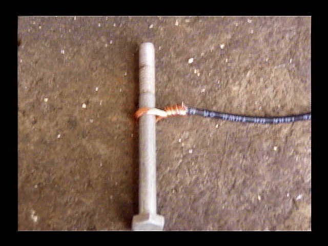
 Strip back the wire approx 1 1/2 inches. Use a 1/4 inch bolt for your
wire eye form. there is no need to make the wire eye tight around the
bolt form as the solder will shrink the eye size enough.
Strip back the wire approx 1 1/2 inches. Use a 1/4 inch bolt for your
wire eye form. there is no need to make the wire eye tight around the
bolt form as the solder will shrink the eye size enough.
 Remove the bolt form, then solder with rosin core. This yields the
cheapest and best wire terminal I know. Lightly tapping on the eye
form on both sides with a hammer, will flatten the eye, and give a very
effective mechanical and electrical junction to the platform.
Remove the bolt form, then solder with rosin core. This yields the
cheapest and best wire terminal I know. Lightly tapping on the eye
form on both sides with a hammer, will flatten the eye, and give a very
effective mechanical and electrical junction to the platform.
 When this has been done to all 4 wires and the wires are connected on the platform side of the platform,
you're ready to put the insulators on. I recommend soldering the
insulator side of the wires. The length of wire
calculated for the frequencies, will need to be slightly added to;
approx 3-4 inches, this allows for the amount of wire used to
fold back, wrap, and solder at both ends. This will allow full strength
with no concern for stress failure.
When this has been done to all 4 wires and the wires are connected on the platform side of the platform,
you're ready to put the insulators on. I recommend soldering the
insulator side of the wires. The length of wire
calculated for the frequencies, will need to be slightly added to;
approx 3-4 inches, this allows for the amount of wire used to
fold back, wrap, and solder at both ends. This will allow full strength
with no concern for stress failure.
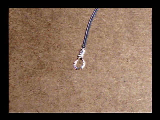
 Strip back the insulation approx 2 1/2 inches and wrap according to
picture.
Strip back the insulation approx 2 1/2 inches and wrap according to
picture.
 Solder with rosin core, and you're ready to tie the short tag line that
will attach antenna leg to one of 4 driven stakes at 4 ground ponts, 90
degrees from each other.
Solder with rosin core, and you're ready to tie the short tag line that
will attach antenna leg to one of 4 driven stakes at 4 ground ponts, 90
degrees from each other.
The material I use to tie the
insulators to their respective ground driven stakes, is good old
fashion 1/8 inch vinal cloths line cord. Buy the cheap stuff that does
not say steel reinforced. Its more than strong enough and widely available.
Support Mast Detail:
Go to Pushup Pole Construction Project